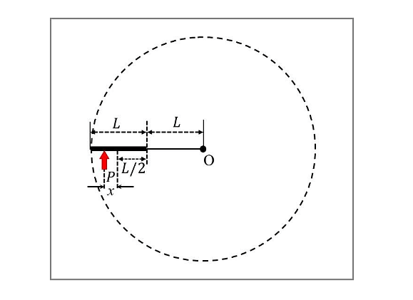
List-I contains four conducting loops lying in the \(XY\) plane, as shown in the figures. The loops are rotating about \(Z\)-axis passing through the point \(O\) with time period \(T\) in clockwise direction. The region \(x>0\) contains a uniform magnetic field \(B\) in the \(+z\) direction. List-II contains the qualitative variation of the induced current \(i(t)\) for each of these loops. Choose the option which describes the correct match between the entries in List-I to those in List-II.
Show Hint
Induced current depends on:
\[
i\propto-\frac{d\Phi}{dt}
\]
If enclosed area changes uniformly:
\[
i=\text{constant}
\]
If enclosed area changes sinusoidally:
\[
i\sim\sin(\omega t)
\]
Step 1: Understanding the Concept:
The fundamental principle involved is Faraday's Law of Induction, which states that an electromotive force (EMF) is induced in a conductor when the magnetic flux linking it changes over time.
The induced EMF (\(\varepsilon\)) is given by:
\[ \varepsilon = -\frac{d\Phi_B}{dt} \]
where \(\Phi_B = \vec{B} \cdot \vec{A} = BA_{\text{in}}\) is the magnetic flux through the loop.
For a loop rotating with constant angular velocity \(\omega = 2\pi/T\), the area \(A_{\text{in}}\) within the magnetic field region (\(x>0\)) changes.
The induced current is \(i = \varepsilon/R\), where \(R\) is the resistance. Step 2: Key Formula or Approach:
For a circular sector of radius \(r\) and angle \(\theta\) entering a magnetic field, the area entering is \(A = \frac{1}{2}r^2 \theta\).
If it rotates at \(\omega\), \(\theta = \omega t\).
Then, \(\frac{dA}{dt} = \frac{1}{2}r^2 \omega\).
The induced EMF is constant while a sector is entering or leaving the field, resulting in square or step-like current pulses. Step 3: Detailed Explanation: Loop P (Semi-disk): As the semi-disk enters the field (from \(t=0\) to \(t=T/2\)), the area increases linearly at a constant rate. This produces a constant positive EMF and thus a constant current. As it exits (from \(t=T/2\) to \(t=T\)), the area decreases at the same constant rate, producing a constant negative current. This corresponds to the square wave shown in Graph (3). Loop Q (60\(^{\circ}\) sector): The loop enters the field, and the flux increases until it is fully inside (\(t = T/6\)). While fully inside, the flux is constant, and \(i=0\). Then it exits, and the current reverses. This corresponds to Graph (2). Loop R (Off-centered sector): Due to the orientation, the flux begins changing immediately but follows a slightly different timing sequence. However, the basic principle of constant flux change during entry and exit remains. It matches Graph (1) where we see pulses separated by zero-current intervals. Loop S (Butterfly shape): This loop consists of two 60\(^{\circ}\) sectors. Both contribute to the EMF. As one sector exits, another enters, leading to a continuous pulse sequence. This matches Graph (4). Step 4: Final Answer:
By analyzing the rate of change of area for each geometry as it sweeps through the \(x>0\) boundary, we match P to 3, Q to 2, R to 1, and S to 4.