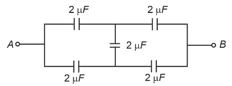
In the following circuit, the equivalent capacitance between terminal A and terminal B is :
- 2 µF
- 1 µF
- 0.5 µF
- 4 µF
The Correct Option is A
Solution and Explanation
To determine the equivalent capacitance between terminals A and B in the provided circuit, a step-by-step analysis of its configuration is performed.
Circuit Configuration:
The circuit comprises four 2 μF capacitors arranged in a diamond configuration:
- Two capacitors are connected in series on the left.
- Two capacitors are connected in series on the right.
- These two series arrangements are connected in parallel between terminals A and B.
1. Left-Side Series Arrangement:
Capacitors: Two 2 μF capacitors in series.
Equivalent series capacitance:
$ \frac{1}{C_{\text{series}}} = \frac{1}{2} + \frac{1}{2} = 1 $
$ C_{\text{series}} = 1 \mu F $
2. Right-Side Series Arrangement:
Capacitors: Two 2 μF capacitors in series.
Equivalent series capacitance:
$ \frac{1}{C_{\text{series}}} = \frac{1}{2} + \frac{1}{2} = 1 $
$ C_{\text{series}} = 1 \mu F $
3. Parallel Arrangement of Series Combinations:
The two resulting 1 μF equivalent capacitors are connected in parallel.
Equivalent parallel capacitance:
$ C_{\text{parallel}} = 1 + 1 = 2 \mu F $
Conclusion:
The equivalent capacitance between terminal A and terminal B is $ 2 \mu F $.
Top Questions on Capacitors and Capacitance
- Energy stored in a capacitor is given by the equation \[ E = \frac{1}{2} C V^2 \] where: - \( C \) is the capacitance, - \( V \) is the voltage, - \( E \) is the energy stored. Given the values of \( C \), \( V \), and \( E \), determine the energy stored.}
- MHT CET - 2025
- Physics
- Capacitors and Capacitance
- Two capacitors $ C_1 = 4\mu F $ and $ C_2 = 6\mu F $ are connected in series across a 60 V battery. The potential difference across $ C_2 $ is:
- BITSAT - 2025
- Physics
- Capacitors and Capacitance
A circuit consisting of a capacitor C, a resistor of resistance R and an ideal battery of emf V, as shown in figure is known as RC series circuit.

As soon as the circuit is completed by closing key S₁ (keeping S₂ open) charges begin to flow between the capacitor plates and the battery terminals. The charge on the capacitor increases and consequently the potential difference Vc (= q/C) across the capacitor also increases with time. When this potential difference equals the potential difference across the battery, the capacitor is fully charged (Q = VC). During this process of charging, the charge q on the capacitor changes with time t as
\(q = Q[1 - e^{-t/RC}]\)
The charging current can be obtained by differentiating it and using
\(\frac{d}{dx} (e^{mx}) = me^{mx}\)
Consider the case when R = 20 kΩ, C = 500 μF and V = 10 V.- CBSE Class XII - 2025
- Physics
- Capacitors and Capacitance
- A parallel plate capacitor is charged by an ac source. Show that the sum of conduction current (\( I_c \)) and the displacement current (\( I_d \)) has the same value at all points of the circuit.
- CBSE Class XII - 2025
- Physics
- Capacitors and Capacitance
- Want to practice more? Try solving extra ecology questions todayView All Questions

