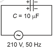
A 10 µF capacitor is connected to a 210 V, 50 Hz source as shown in figure. The peak current in the circuit is nearly (π = 3.14) :
 :
:
:- 0.58 A
- 0.93 A
- 1.20 A
0.35 A
The Correct Option is B
Solution and Explanation
Capacitive Reactance
$$ X_C = \frac{1}{\omega C} = \frac{1}{2 \pi f C} $$
$$ X_C = \frac{1}{2 \times 3.14 \times 50 \times 10 \times 10^{-6}} = \frac{1000}{3.14} $$
$$ V_{rms} = 210 \ V $$
$$ i_{rms} = \frac{V_{rms}}{X_c} = \frac{210}{X_c} $$
Peak current \( = \sqrt{2} i_{rms} \)
$$ = \sqrt{2} \times \frac{210}{1000} \times 3.14 = 0.932 \simeq 0.93 \ A $$
Top Questions on Capacitors and Capacitance
- Energy stored in a capacitor is given by the equation \[ E = \frac{1}{2} C V^2 \] where: - \( C \) is the capacitance, - \( V \) is the voltage, - \( E \) is the energy stored. Given the values of \( C \), \( V \), and \( E \), determine the energy stored.}
- MHT CET - 2025
- Physics
- Capacitors and Capacitance
- Two capacitors $ C_1 = 4\mu F $ and $ C_2 = 6\mu F $ are connected in series across a 60 V battery. The potential difference across $ C_2 $ is:
- BITSAT - 2025
- Physics
- Capacitors and Capacitance
A circuit consisting of a capacitor C, a resistor of resistance R and an ideal battery of emf V, as shown in figure is known as RC series circuit.

As soon as the circuit is completed by closing key S₁ (keeping S₂ open) charges begin to flow between the capacitor plates and the battery terminals. The charge on the capacitor increases and consequently the potential difference Vc (= q/C) across the capacitor also increases with time. When this potential difference equals the potential difference across the battery, the capacitor is fully charged (Q = VC). During this process of charging, the charge q on the capacitor changes with time t as
\(q = Q[1 - e^{-t/RC}]\)
The charging current can be obtained by differentiating it and using
\(\frac{d}{dx} (e^{mx}) = me^{mx}\)
Consider the case when R = 20 kΩ, C = 500 μF and V = 10 V.- CBSE Class XII - 2025
- Physics
- Capacitors and Capacitance
- A parallel plate capacitor is charged by an ac source. Show that the sum of conduction current (\( I_c \)) and the displacement current (\( I_d \)) has the same value at all points of the circuit.
- CBSE Class XII - 2025
- Physics
- Capacitors and Capacitance
- Want to practice more? Try solving extra ecology questions todayView All Questions

