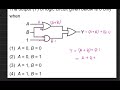
To ascertain when the output \( Y \) of the provided logic circuit is 0, we examine its components and their operation with inputs \( A \) and \( B \).
Step 1: Logic Gate Identification Circuit Analysis: - An OR gate receives inputs \( A \) and \( B \). - A second OR gate takes the output of the first OR gate and a constant input 1. - An AND gate receives inputs \( A \) and \( B \); its output is fed into the final OR gate.
Step 2: Circuit Behavior Analysis 1. The first OR gate outputs 1 if \( A = 1 \) or \( B = 1 \). Its output is 0 only when \( A = 0 \) and \( B = 0 \). 2. The second OR gate has a fixed input of 1. As an OR gate outputs 1 if any input is 1, this gate will consistently output 1, irrespective of the first OR gate's output. 3. The AND gate outputs 1 only when both \( A = 1 \) and \( B = 1 \). In all other scenarios, it outputs 0. 4. The final OR gate determines \( Y \), receiving inputs from the AND gate and the second OR gate. Since the second OR gate always outputs 1, \( Y \) can only be 0 if the other input (from the AND gate) is also 0.
Step 3: Condition for \( Y = 0 \) For \( Y \) to be 0, the input conditions must result in the AND gate outputting 0. This occurs when \( A = 0 \) and \( B = 0 \).
Therefore, the necessary condition is:
\[ A = 0, \, B = 0. \] Consequently, option (2) is correct.