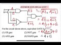
The logical operations of this circuit are analyzed sequentially to determine the equivalent gate.
1. Initial Operation: Inputs $ A $ and $ B $ are processed by a NAND gate. The output of this gate is the negation of the logical AND of $ A $ and $ B $. The expression for this output is:
$ \overline{A \cdot B} $
2. Parallel Operation (Upper Path): Input $ B $ is also passed through a NOT gate, resulting in:
$ \overline{B} $
3. Intermediate Operation (Upper Path): The outputs from step 1 ($ \overline{A \cdot B} $) and step 2 ($ \overline{B} $) are combined using an AND gate. The output is:
$ (\overline{A \cdot B}) \cdot (\overline{B}) $
4. Parallel Operation (Lower Path): Inputs $ A $ and $ B $ are processed by an OR gate. The output is:
$ A + B $
5. Intermediate Operation (Lower Path): The output from step 4 ($ A + B $) is inverted by a NOT gate. The output is:
$ \overline{A + B} $
6. Final Combination: The outputs from step 3 ($ (\overline{A \cdot B}) \cdot (\overline{B}) $) and step 5 ($ \overline{A + B} $) are combined using an OR gate to produce the final output $ Y $:
Boolean Algebra Simplification: Applying De Morgan's Law to $ \overline{A \cdot B} $, we get $ \overline{A} + \overline{B} $. Substituting this into the expression for $ Y $: